| |
 |
 |
Safety Concerns in Geotechnical Engineering -- 3D Crack Monitoring
Sudhir Kumar Tewatia
Researcher,Central Soil & Materials Research Station, Ministry of Water Resources, Outer Ring Road, Hauz Khas, New Delhi, India
Email
and
K. Venkatachalam
Researcher and Director respectively, Central Soil & Materials Research Station, Ministry of Water Resources, Outer Ring Road, Hauz Khas, New Delhi, India
Email
|
ABSTRACT
Swelling soils in the foundations may pose the problem of inducing damaging cracks in civil engineering structures. Underground excavations are often required in geotechnical engineering not only for hydro-power projects but for roads and railways etc. also. Besides the head-race, tail-race and access tunnels and power house caverns, cavities are also required for transformers, galleries, de-silting chambers and other accessories. Cracks may appear in civil engineering structures, such as buildings, cavities, the body of dam, its galleries, adjoining tunnels and power plants etc. during or after the construction. Swelling soils in the foundations, redistribution of stresses in the cavities/tunnels etc., creep of the materials, earthquake or some other vibrations etc. may be just a few of the many other reasons for the cracks. The relative movements of the walls along and across the crack, and perpendicular to the plane of cracking surface or wall, beyond certain limits, may prove to be potentially damaging. For the considerations of safety and maintenance, the measurement of the magnitude and time rate of deformation of the cracks is essential. Instruments play a vital role during construction of underground structures. Instrumentation for deformation monitoring is of vital importance especially in underground excavations in complex geological formations. However, the purpose of an engineer is to increase the safety and to reduce the cost. 3D crack-monitor is generally used for 3D crack-monitoring. A simple method is suggested here that does not require 3D crack monitor. The method provides an in-built check on the accuracy of method, results and observations.
INTRODUCTION
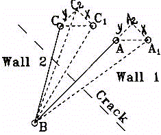
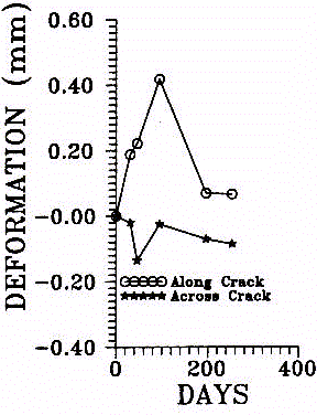
At Bundi, Rajasthan, India, soil often found is the black cotton soil clayey soil which seasonally swells and shrinks enormously, often inducing cracks in buildings and other civil engineering structures if no proper foundation treatment is done prior to construction. At Sardar Sarovar Dam Project on Narmada River (India) an underground powerhouse was being constructed. At both these places, the Central Soil and Materials Research Station (CSMRS) had been doing three-dimensional crack monitoring using 3-D crack monitor, shown in Figure 1 (Mathur et al. 1995). It consists of a hollow cube (of about 5 cm sides) mounted on a fixing plate and 3 plates joined in 3 mutually perpendicular directions mounted on a fixing plate as shown in figure. The cube and 3 plates are fixed on opposite sides of crack so that 3 mutually perpendicular faces of the cube are parallel to the plates and all the 3 plates are either parallel or perpendicular to the direction of crack. The distance between the 3 parallel faces, of the cube and the plates, is measured by dial gauge through the holes, one each in three plates, after certain time intervals, for measuring the deformation of the cracks in three mutually perpendicular directions. Tewatia (1997) has recently suggested a new 3-pin method shown in Figures 2 and 3, using digital vernier calipers of 0.01 mm least count, for two-dimensional crack monitoring. In this paper this method has been further modified as 4-pin method for three-dimensional crack monitoring. The proposed method does not make use of 3-D crack monitor and provides an in built check on the accuracy of results and observations.

Figure 1. 3D Crack Monitor (Mathur et al. 1995)

Figure 2. The 3 Pin Method for 2D Crack Monitoring (Tewatia 1997)

Figure 3. A Typical Plot of Crack Monitoring at Sardar Sarovar
Power House Cavern, India (Tewatia 1997)
RECENTLY PROPOSED 3 PIN METHOD
In this recently proposed 3 pin method (Tewatia 1997), insert 3 pins A, B and C on both sides of the crack as shown in Figure 2, so that AB is perpendicular to the direction of crack and BC is inclined at any known angle, a. Measure original lengths of AB and BC. Suppose after time, t1, A moves to A1 and C moves to C1 so that BA1 and BC1 are the new lengths of BA and BC respectively. The basic assumption involved in the method is that the walls move as rigid bodies without any rotation so that AA1 is equal and parallel to CC1, and therefore the components of these along and across the crack, x and y (say), are equal. The approximate value of y (= BA1 - BA) is assumed.
Now in triangle BCC2: BC and CC2 (= y) are known in magnitude and direction therefore magnitude and direction of BC2 can be found. In triangle BC1C2: as directions of C1C2 (which is parallel to crack) and BC2 are known, therefore, angle between them is known. As in this triangle magnitudes of two sides BC1 and BC2 and one angle are known, therefore third side C1C2 (= x) can be determined.
Using this x in right angled triangle BA1B2, BA2 is determined as (BA12 - x2)/2. New value of y is determined as (BA2 - BA). As compared to the previous y, this y is closer to the true value. Using this y from triangles BCC2 and BC1C2, new value of x is determined as earlier. As compared to the previous x, this x is closer to the true value. Using this new x, new y is determined from triangle BA1A2 as earlier which is further closer to the true value as compared to previous y. Repeating this procedure, after 5-6 iterations, the values of x and y converge to their true values. A very simple software can be developed on these lines for successive iterations (calculations).
MODIFICATION OF THE METHOD FOR 3-D CRACK MONITORING
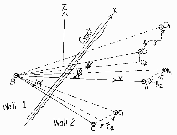
In Figure 4 one more pin, D, at known height, DD2, above the plane of wall, is inserted so that original length, BD, its angle with the plane of the wall, f, and the angle (b) between the projection of BD on the plane of wall, BD2, and the side BA are known. Let z is the component of relative movement of walls in the direction, which is perpendicular to the plane of the wall. The lines BA and BC, lying in the plain of wall are not much affected by the deformation in z direction. However, the relative movement of point D with respect to B is affected by x, y and z components. As original length of BD and its length, BD1, after certain time, t, are known; x and y components can be determined from BA and BC; therefore, by solid geometry/trigonometry, z component can be evaluated.

Figure 4. The Proposed 4-Pin Method for 3D Crack Monitoring
Now this z correction is applied to the measured values of BA1 and BC1. As the measured values of BA1 and BC1 are increased due to the deformation in z direction, which was neglected in the initial value, therefore new values of these are corrected as
BA1 = (BA12 – z2)/2 and BC1 = (BC12 – z2)/2
Using these values, x and y components are again calculated as earlier. New values of these, as compared to previous ones, are closer to their true values. Similarly z is again found using these new values of x and y. This value of z is closer to the true value as compared to the previous one. This procedure of finding x, y and z is repeated again and again. The values of x, y and z will generally converge in 4-5 iterations. For obtaining a check on the accuracy of results, procedure can be repeated by inserting one more pin, E, (like D) for evaluating x, y and z components using the pins A, B, C and E. If the method, observations and calculations are correct then the two sets should give the same result. Simple software can be easily designed on these lines.
DISCUSSION AND CONCLUSIONS
For evaluating the angle (a) one needs not measure it with the protractor. Measure all the sides of triangle ABC with the digital vernier calipers. By simple geometry we know that all the angles of a triangle are known if the magnitudes of all of its sides are known. Similarly for finding height of point D, angle a and angle b; basic principles of solid geometry/trigonometry can be used after measuring the distance of point D from A, B and C which lie in a plane. Usually these angles should be 30-45 degrees for good results.
The proposed method has two advantages over 3D crack monitor. First - it reduces the cost of these instruments. A number of 3D crack monitors are required to be fixed permanently at various points where ever monitoring of deformations is required. Second – 3D crack monitor does not provide a check on human or other errors (if any) in observations and hence results, like this method.
REFERENCES
Mathur, R. K., Verma, S. K., Dhawan, A. K. and Sharma, V. M. (1995), “Recent Developments in Instrumentation/Measuring Techniques – 3D Crack Monitor,” Conference on Design and Construction of Underground Structures, V.M. Sharma and K.R. Saxena Editors, at Central Soil and Materials Research Station, New Delhi, 23-25 February 1995,
Tewatia, S. K., 1997, "Crack Monitoring in Underground Construction," First Asian Rock Mechanics Symposium in Seoul, Korea, on "Environmental and Safety Concerns in Underground Construction," Lee, Yang and Chung editors, Balkema Publishers, Rotterdam, Neatherlands, pp.785-787.


